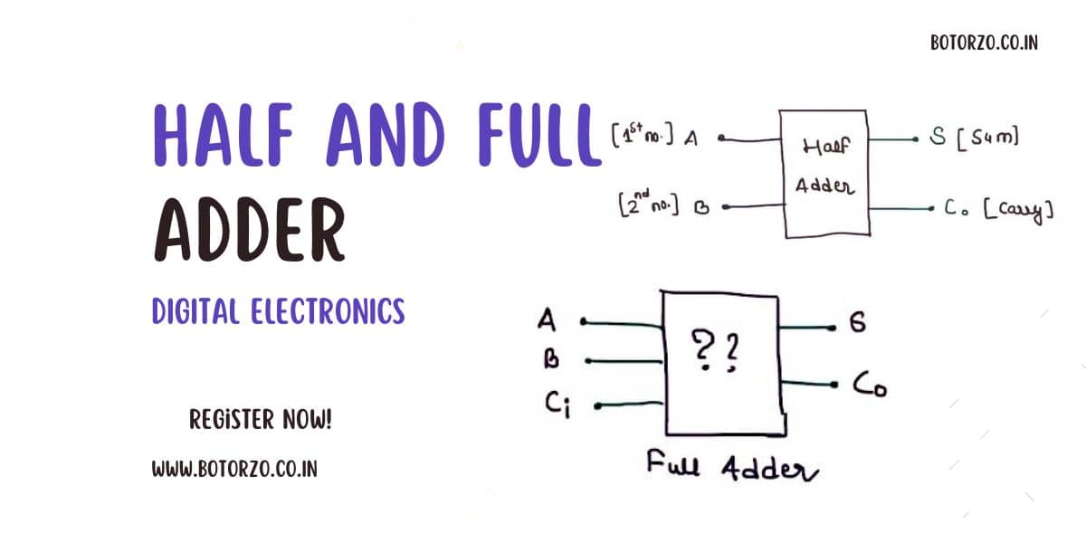
Half Adder
A combinational circuit is one in which the output is only dependent on the present input. As a result, the output, which is our sum and what we carry, is also dependent on the two numbers that we are trying to add in half and full adder.
what is and Why it is called half-Adder?
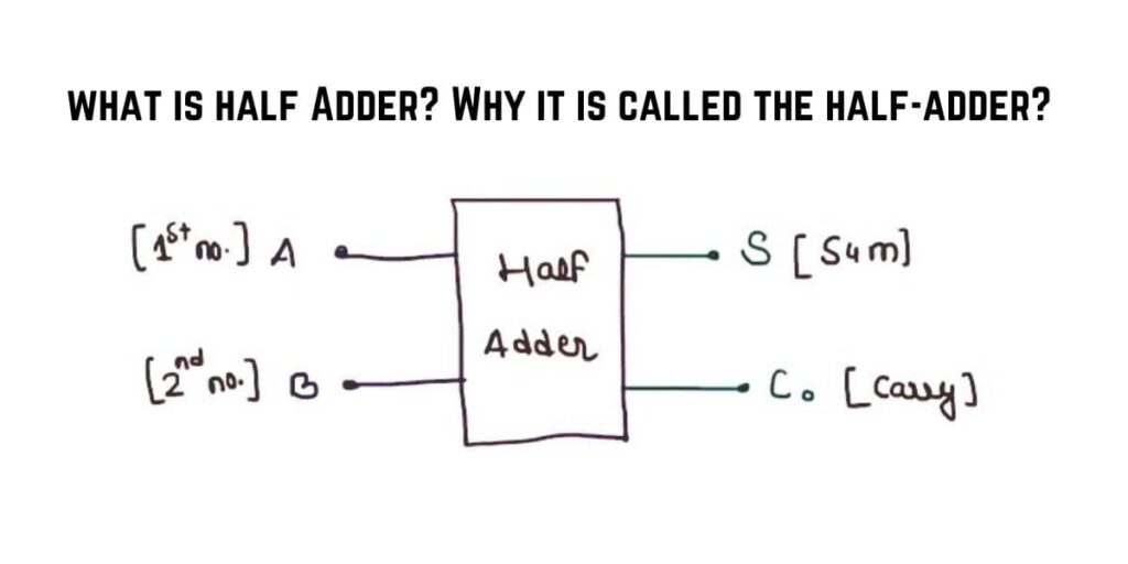
The 1st and most important point in the half-adder is that it is used to add a single bit number, and the second point is that it Does not take carry From the Previous sum.
OK, so these two points are there which describe the half-adder. Only a single big number is added by using it, which means that, if you are adding A and B, A is having only a single bit, and B is also a single-bit number. And one more thing is that it does not take carry from the previous sum.
For this, we will make a truth-table, because there are two inputs. We are having four possible combinations. So A and B, this is two number, single bit that we want to add. “S” is your sum, and “Co” output is your carry.
Read More Topic Related To Engineering
Truth Table Of Half Adder
| A | B | S | Co |
|---|---|---|---|
| 0 | 0 | 0 | 0 |
| 0 | 1 | 1 | 0 |
| 1 | 0 | 1 | 0 |
| 1 | 1 | 0 | 1 |
What we are getting at the sum and carry
Now we want the expression for the sum and expression for the carry output so that we can make a circuit that acts as a half Adder.
So the sum is what it is actually an XOR operation because it is an odd one detector. Whenever the combination has an odd number of ones, the output is high, and it is the property of the XOR. So instead of making KMAP or any other thing, we can directly write sum as :
(1)
Similarly, they carry output A.B, because it is high only when “A” is high and “B” is high.
Half Adder Circuit
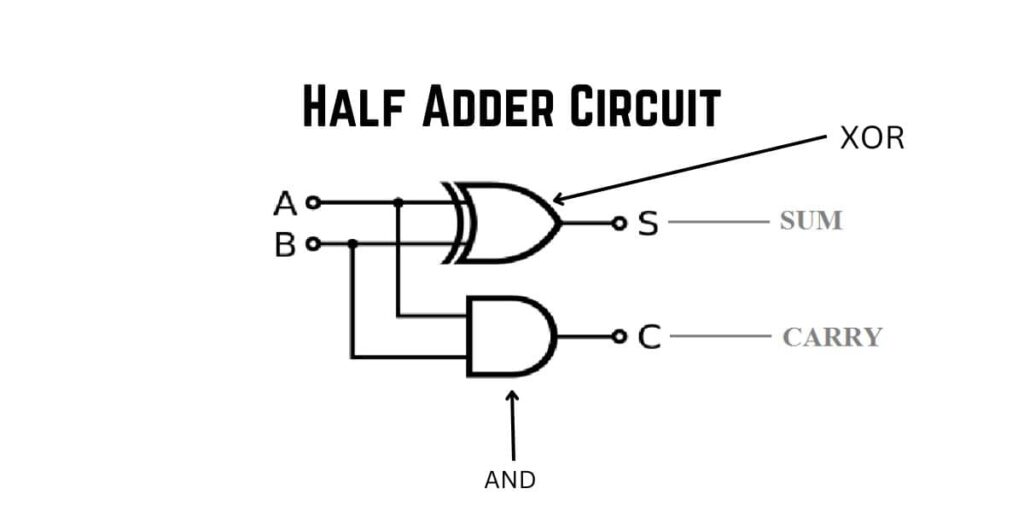
And this logic is inside this box. Sum is “S” taken from the XOR gate and Carry is “Co” taken from the “And” gate. So this one is your half-adder. And this circuit is inside this, this box. And the two are two inputs, A B, and the two outputs. So this is all that you need to know about the half adder.
Full Adder
Now, we are going to find out the logical expression for your sum and the logical expression for your output carry for Full-Adder,
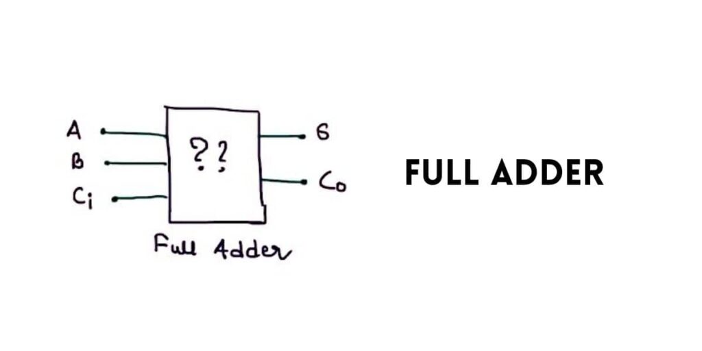
This box you can see here is your full-adder. And what is inside this box? Actually, the combination of your logic gates, we don’t know. And you can see that A B&C are the three inputs to this full adder,
and the sum “S” and your carry “Co” are the two outputs of your full-adder. now we are going to find out the logical expression Or you can say that the combination of the gate inside this box. will do it by using the Kmap.
Truth Table Of Full Adder
| A | B | Ci | S (Sum) | Co (Carry) |
|---|---|---|---|---|
| 0 | 0 | 0 | 0 | 0 |
| 0 | 0 | 1 | 1 | 0 |
| 0 | 1 | 0 | 1 | 0 |
| 0 | 1 | 1 | 0 | 1 |
| 1 | 0 | 0 | 1 | 0 |
| 1 | 0 | 1 | 0 | 1 |
| 1 | 1 | 0 | 0 | 1 |
| 1 | 1 | 1 | 1 | 1 |
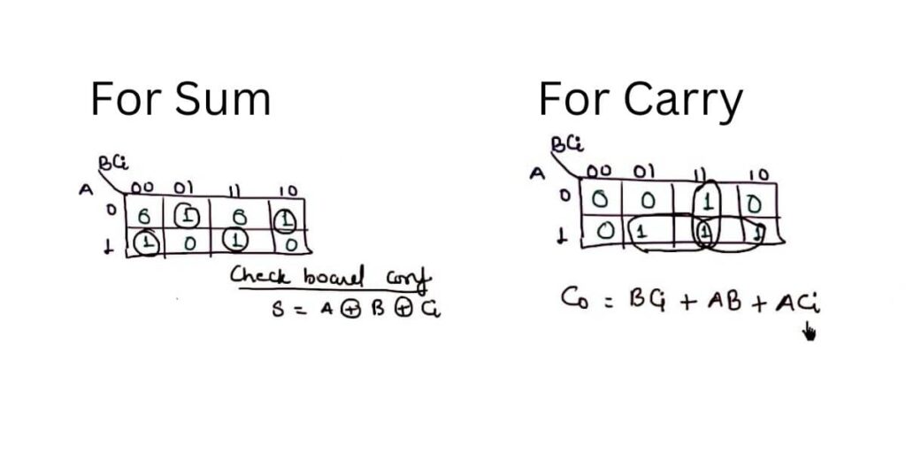
Now you can see here that a very interesting pattern appears. Why did interesting? Because you will find that you cannot group any of the ones together in the first map. And this particular pattern we call checkboard configuration.
You have to remember one thing in the checkboard configuration, which is that whenever it appears, the output, the sum is equal to the XOR combination of all input. For example, if we were having the four input ABCD and the sum should be :
(2)
Sum and carry is shown in image :
(3)
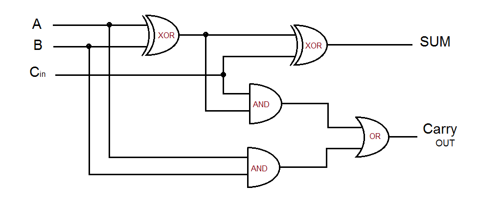
Full Adder Circuit
Our Another Domains Vidyapedia.in And Uietmdu.in

