In this article, we are going to discuss the introduction of a block diagram.
Some important points of block diagrams
- So point number one is block diagrams are a pictorial representation of a control system.
- Block diagram representation is used to build a mathematical model of the control system, which can be emulated on a computer. It is an excellent point to understand. Nowadays, systems are analyzed on computers by the use of the software. In that case, block-diagrams representation plays an important role because it can help build a mathematical control system model.
- Representation is used to calculate the overall transfer function of the system. As we all know that to find out the output with respect to any given input, many transfer function of the system and block diagrams representation helps to find out the overall transfer function of the system.
Elements of a canonical form of a closed-loop system.
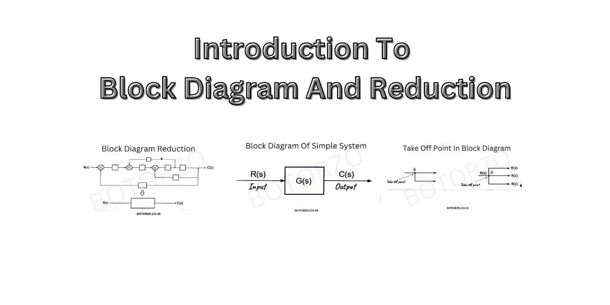
We will start with the basic representation of a control system. And we all know this representation consists of a block having two arrows.
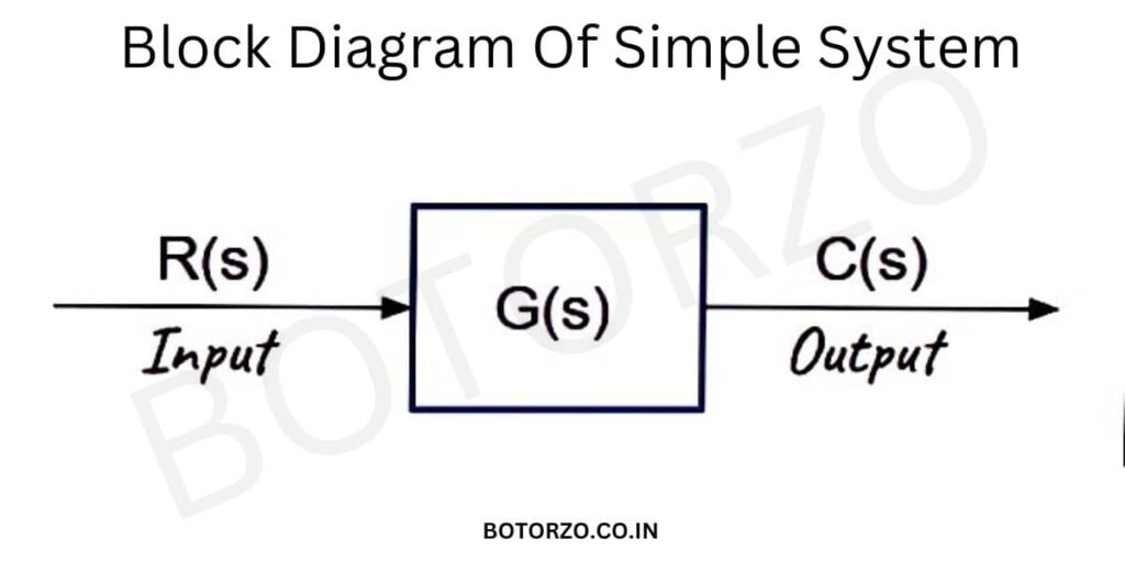
- The arrow of the signal which goes into the block represents the input.
- The signal which goes out of the block represents the output,
- and the block itself represents the transfer function of the system.
But this is the basic representation of the control system. Practically control systems are more complex in nature. They consist of multiple subsystems in the connection of many blocks, which are connected with branches and arrows. So to analyze those complex representations, we need to discuss some more elements of canonical form of a closed-loop system, like summing points and take-off points.
Summing point
A summing point, or a summing junction represents the dynamic summation of two or more signals. So we want to add two or more signals in a, We will use a summing point.
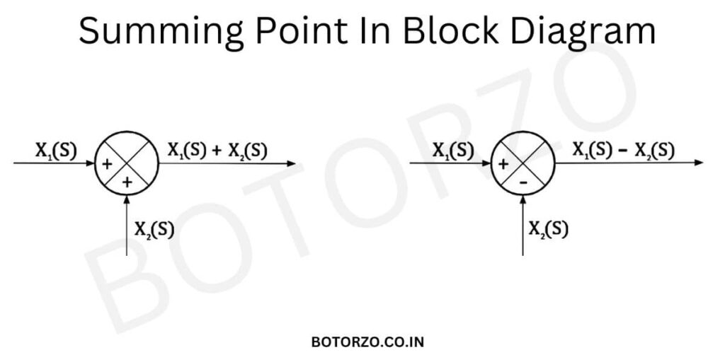
This is the symbol of a summing point, which is used to add two signals. If this signal is X1(s), and this signal is X2(S), then the resultant signal will be X1(s) + X2(S).
X=X1(s) + X2(S).
On the other hand,
X=X1(s) – X2(S).
The polarity plays a very important role here. If the polarity is positive, then we signal will be positive. If the polarity is negative, then the signal will also be negative. In the first case, the polarity of both signals is positive, And hence, these signals are added with a positive sign. In the second case, the polarity of one of the signals is negative, and hence it is added with a negative sign.
Since we are using the summing point, or the summing junction, in order to add more signal, the summing point can be called an adder point. So now we are done with the discussion on the summing point.
Take-off point
The take-off point is also called a branch point. So the take-off point represents a point where the signal branch is out and goes concurrently to the other blocks or can say that the take-off point is a point where the signal distributes to several other branches.
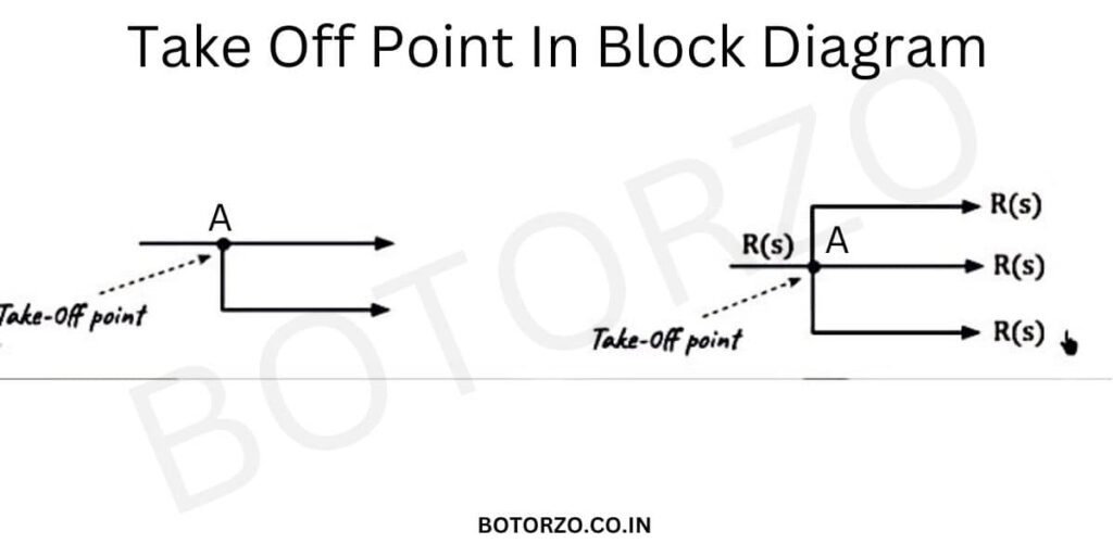
Let us understand this with the help of this diagram. the signal distributes into two branches. So point “A” is called as the take-off point. Similarly, in the 2nd block-diagram, Point “A” is the take-off point.
As this point distributes this signal into these three branches. If this signal is R(S), then we can distribute this signal among three branches. So this is the basic use of a take-off point in a block diagram. It distributes the signal from one branch into several other branches.
| Related Topic To Block Reduction |
|---|
| Block Diagram Reduction Technique |
| Block Reduction Rules |
| Read More Topics Related To Control System |
Reduction of multiple subsystems / Block Reduction Diagram
practical control systems are complex in nature. It consists of multiple subsystems. And in order to find out the overall transfer function, we need to reduce those multiple subsystems into a single block. We will discuss the topic of the reduction of multiple subsystems.
In order to calculate the output with respect to any given input, we need the overall transfer function of the system. The transfer function is an important parameter in order to find out the output with respect to any given input.
when the system is complex, that is, it is having multiple subsystems, then we need to reduce the complex representation into a single block. And then only we will be able to determine the overall transfer function of the system.
So now we can have the idea that the primary target is to find out the overall transfer function of the system. Let us take an example of a practical control system.
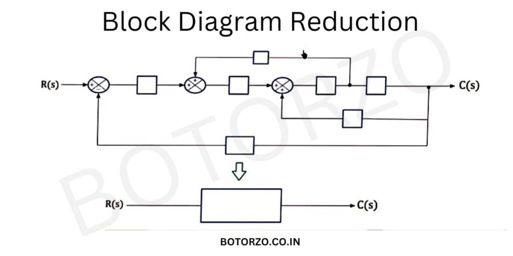
This is a practical control system Consisting of multiple subsystems. It consists of the interconnection of different blocks connected with different branches and arrows. And suppose you want to calculate the overall transfer function of these multiple subsystems.
In that case, we need to convert this overall system into a single blocks, where this block represents the overall transfer function and the procedure by which we can reduce this complex representation into a simple structure called as block algebra diagram or Block Reduction.
| Referring Websites |
|---|
| UIETMDU.IN |

1 thought on “Introduction To Block Diagram And Reduction”
Comments are closed.