In this article, we will see the “prove gains are multiplied.” Rule #2: When blocks are connected in series or cascaded, then the gains are multiplied by each other for each block.
any control system in which two blocks are connected in series with different gains. Then the gain of the overall system can be computed by multiplying the gains of individual blocks.

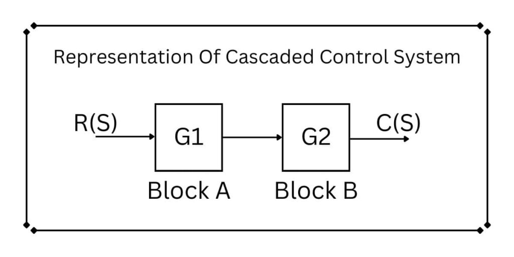
Let us assume the control system as given in the above diagram. The input is R(S), and the output is C(S). Two different blocks are connected in series, which are blocks “A” and Block “B”. The gain of Block A is G1. And Block B’s gain is G2.

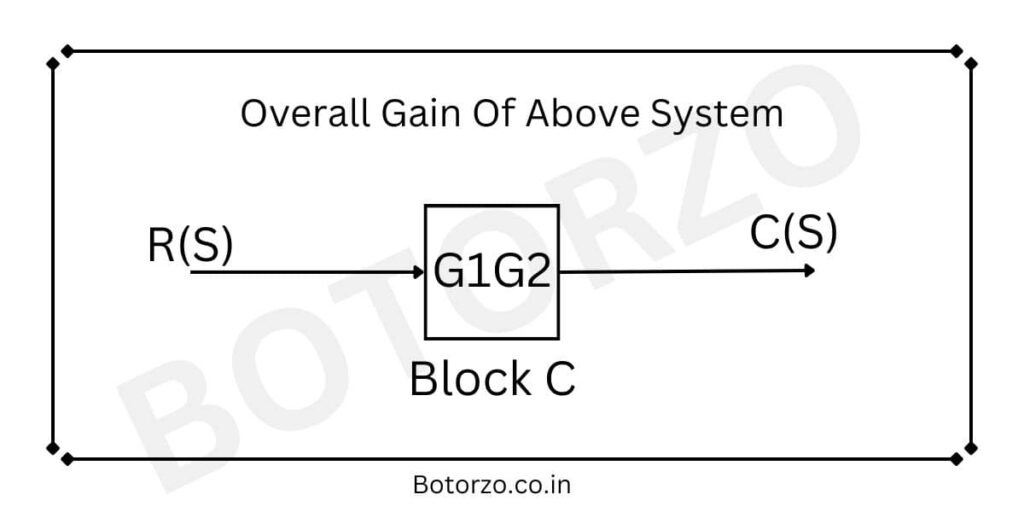
From the statement of the block diagram reduction rule, if two or more blocks are connected in series, the overall gain of the system is equal to the product of the gains of the individual blocks, also shown in the above diagram.
Read More Topic From Control System
Prove Gains Are Multiplied

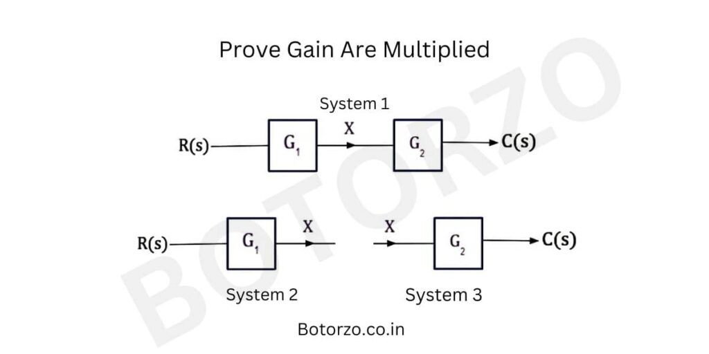
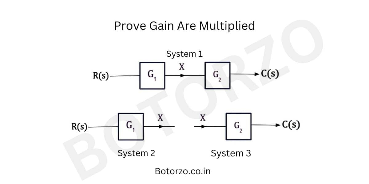
In the above diagram, system 1 has input R(S) and output C(S), having two blocks connected in cascaded or In a series connection, the gain of the first block is G1, and the gain of the Second block is G2. System 1 can be divided into two subsystems, System 1 and System 2.
From System 1
Transfer Function Of System 1
G1=X(s)/R(S) =X/R
Form system 1 The output is X, and the input is R. And the transfer of function, or the gain of the system, is G1. Hence we can easily calculate the transfer function of the system, which is the Laplace transform of output divided by the Laplace transform of input. The transfer function G1 can be expressed as above.
From System 2
G2=C(S)/X(S) =C/X
from System 2. The transfer function of the system is G2. The input is X, and the output is C. Hence the gain of the system can be easily calculated, as written above.
From System 1
The transfer function of system 1 is C(S)/R(S).
If the rule of block diagram reduction is true, then the transfer function of the system should be equal to G1G2.
C(S)/R(S)=G1G2 ————— eq(1)
From Two Sub System
But G1G2= (X/R) * (C/X) =C/R ———-eq(2)
Hands equation 1 and equation 2 are equal.
Whenever the blocks are connected in series or in a cascading manner, then the gain of these blocks can be multiplied by each other. The overall gain can be represented by a single block. Complex control blocks can be reduced to simple blocks by the “block diagram reduction method.”
If the system is having more than two blocks
Assume the system contains more than two blocks, each with a different gain (G1, G2, and G3). The overall gain of the system can then be easily calculated using the method described above.
The overall gain of the system is= G1G2G3.
If N blocks are connected in series
If the system contains “N” blocks, then the gain of the system is the multiplication of the gain of each individual block up to “N” times.
Gain=G1G2G3………..GN
Conclusion
The above method can be applied to both open-loop systems and closed-loop control systems. The main difference is that an open loop system does not have any type of feedback, so the transfer function or gain is the same, which can be easily calculated by Multiplying the gain of individual blocks and if the system has feedback named a closed loop system, then First we have to calculate the gain of the system and then the transfer function.
For negative and positive feedback the transfer function is different from the sign term.

